Allen Bradley KF3 (DH 485)
The following information applies to SLC 500 PLCs on the DH-485 network interface via a KF3 Module. Connection is via the RS-232 port on the KF3 Module. The PROTOCOL CAN COMMUNICATE DIRECTLY INTO THE PROGRAMMING PORT ON THE slc 500 plc.
Details on the Device Address can be found in the Device Properties Information Topic.
External Address Format
External Address is an ascii string which exactly references an item of data within the PLC. It can be entered at configure time as a text string, and will be validated by the system before use. For this protocol the external address has the following format:
N - Dec number 0 - 9
|
File Type |
File Number |
Delimiter |
Start Address |
Delimiter |
Address Offset |
|
O |
NNN |
: |
NNN |
|
|
|
I |
NNN |
: |
NNN |
|
|
|
S |
NNN |
: |
NNN |
/ |
NN |
|
B |
NNN |
: |
NNN |
/ |
NN |
|
T |
NNN |
: |
NNN |
/ |
NN |
|
C |
NNN |
: |
NNN |
/ |
NN |
|
N |
NNN |
: |
NNN |
|
|
Note that file number is variable length of up to 3 decimal digits.
Offset Format
The software also allows an item of data within the PLC to be referenced by means of a table selection and an offset. The following table shows the offset and table formats for the SLC 500 PLC type:
|
Table |
External Address Type |
Type |
Offset Format |
Offset Range |
Privilege R = Read W = Write |
Description |
|
O0 |
O0 |
Word |
NNN |
000-999 |
RW |
Outputs table |
|
I1 |
I1 |
Word |
NNN |
000-999 |
R |
Inputs table |
|
S2 |
S2 |
Bit |
NNN/NN |
000/00-999/15 |
R |
Status table |
|
B3 |
B3 |
Bit |
NNN/NN |
000/00-999/15 |
RW |
Bit table |
|
T4 |
T4 |
Word |
NNN/NN |
000/00-999/02 |
RW |
Timer table |
|
C5 |
C5 |
Word |
NNN/NN |
000/00-999/02 |
RW |
Counter table |
|
N7 |
N7 |
Word |
NNN |
000-999 |
RW |
Integer table |
Other tables can be added by using device specific properties within the configuration software.
Property Pages
The following device advanced properties page exists for an Alan Bradley device:

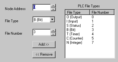
Node address is a two digit decimal number which is the KF3 network address of the PC itself. Its range is 00-31. The address 00 is usually used for the PC, other addresses being reserved for PLC device addressing.
New PLC files can be added to the system to introduce new tables. A file type is selected from the drop down box and a file number is entered. The ‘add’ button is then used to transfer the file to the list on the left. The default files cannot be removed from the system, only ones which have been added by the user. Only bit, integer, input and output file types can be added. New file numbers have a range of 3-255.
Protocol Compatibility
A file running on the SLC 500 PLC represents a PLC table. A file is described by a file type and a file number. The following files are always present by default on the PLC, others may be added by the PLC programmer:
|
File Type |
Opcode |
File Number |
|
Output |
O |
0 |
|
Input |
I |
1 |
|
Status |
S |
2 |
|
Bit |
B |
3 |
|
Timer |
T |
4 |
|
Counter |
C |
5 |
|
Integer |
N |
7 |
Input, output and integer files are all word file types. Only a PLC starting address is specified since the whole word is read from the PLC. The input and output tables reference data held in physical input and output cards fitted into the PLC. The cards themselves hold a minimum of one word of data. The External Address in no way references the slot number of the card itself , instead it references the word number in the input or output file. Write access to input data is not supported.
For Example
|
Power Supply |
C P U |
1 |
2 |
3 |
4 |
5 |
|
|
Slot 1 |
: |
Input Module |
16 Bits |
I1 |
: |
000 |
|
Slot 2 |
: |
Output Module |
16 Bits |
O0 |
: |
000 |
|
Slot 3 |
: |
Output Module |
32 Bits |
O0 O0 |
: : |
001 002 |
|
Slot 4 |
: |
Input Module |
32 Bits |
I1 I1 |
: : |
001 002 |
|
Slot 5 |
: |
Output Module |
16 Bits |
O0 |
: |
003 |
The position of the Words within the input and ouput files start from the card on the left and move right. This form of addressing differs from the programming software, which addresses words based on the slot number and offset with the slot.
Bit and status files are bit file types. The start address component of the external address points to the target word. The address offset component is then used to specify an individual bit within that word. Write access to Status data is not supported.
Timer and counter files are both word file types. The start address component of the external address points to the timer or counter structure. The address offset is used to specify one of 3 words that exist in the structure, as follows:
Timer Data
|
|
Offset |
Definition |
|
|
00 |
Status and Internal Usage |
|
|
01 |
Preset Value |
|
|
02 |
Accumulator |
Counter Data
|
|
Offset |
Definition |
|
|
00 |
Status and Internal Usage |
|
|
01 |
Preset Value |
|
|
02 |
Accumulator Value |
A bit type table such as ‘S2’ or ‘B3’ will support the configuration of point types bigger than a bit. If a 16-bit point is configured for example, 16 bits will be read from the table to fill the point. A drive out to a multiple bit point will work, but only if the point starts on a word boundary, if not a comms error will occur. Single bit drive outs work in all cases. All driveouts to the status table will fail as it is read only.
A word type table such as ‘N7’ supports the configuration of smaller or bigger point types. All larger point types will read the required number of words to fill the point. Byte type points will scale down the word to fit it into a byte. Bit type points allow the selection of a bit offset to reference the required bit from the word (0-15). In the case of bit selection points, drive outs will perform a read/modify/write operation as the protocol does not support a bit set operation in this case. All driveouts to the inputs table will fail as it is read only.
The timer and counter word tables do not support the configuration of larger point types. This is because each word location actually contains a three-word structure, and reading more than one of these words into a larger type makes no sense.
Port Settings
Port settings are configurable for the PLC itself within the PLC programming software. The following shows a typical port setup:
RS232
|
|
Baud Rate |
19200 |
|
|
Data Bits |
8 |
|
|
Stop Bits |
1.0 |
|
|
Parity |
Even |
Wiring Information
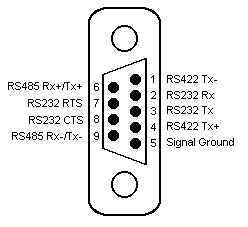
Connection of the PLC to a panel will be via either COM1 or COM2, using RS232 communications. The panel pin out diagram is shown below:
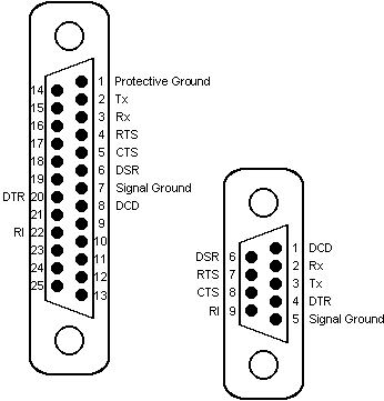
Connection of the PLC to a PC running OPC Server will be via any available COM port, which may be either 25 pin or 9 pin depending on what is available. The COM port pin out is shown below:
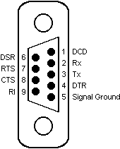
The SLC500 PLC has two methods of connection, either through the RS232 port on the PLC itself, or by connection to a KF3 module on a DH4854 network, also by RS232 communications. The RS232 port on the PLC has the following pin out:
The KF3 module has a 25 pin d-type connector, with the following pin out:
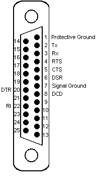
The following shows the correct wiring for connection to the SLC500 PLC via the RS232 port:

Connection to the KF3 Module requires the following wiring:

Examples
Example 1
To read a Word from the default integer file enter:
|
External Address |
N7:001 |
Example 2
To read the Accumulator on timer number 4 enter:
|
External Address |
T4:004/02 |