Control Techniques
The following format applies to the Control Techniques Unidrive PLC.
Details on the device address can be found in the Device Properties Information Topic.
External Address Format
External Address is an ascii string which exactly references an item of data within the PLC. It can be entered at configure time as a text string, and will be validated by the system before use. For this protocol the External Address has the following format:
N - Dec number 0 - 9
|
Addressing Menus | |
|
Menu Number |
Parameter Number |
|
NN |
NN |
Offset Format
The software also allows an item of data within the PLC to be referenced by means of a table selection and an offset. The following tables show the offset and table formats for the Unidrive PLC:
|
|
External Address Type |
Type |
Offset Format |
Offset Range |
Privilege R = Read W = Write |
Description |
|
Menu 1 |
01 |
Configurable |
NN |
01-50 |
RW (R 1-3, 11-13, 17, 35-47, 49-50) |
Speed References |
|
Menu 2 |
02 |
Configurable |
NN |
01-41 |
RW (R 1, 32-41) |
Ramps |
|
Menu 3 |
03 |
Configurable |
NN |
01-31 |
RW (R 1-4, 26-27) |
Frequency slaving, Speed Loop, Encoder Input |
|
Menu 4 |
04 |
Configurable |
NN |
01-20 |
RW (R 1-4, 17-20) |
Current Control |
|
Menu 5 |
05 |
Configurable |
NN |
01-33 |
RW (R 1-5, 23) |
Machine Control |
|
Menu 6 |
06 |
Configurable |
NN |
01-38 |
RW (R 22-29, 35-36) |
Drive Sequencer/Emulator and Timers |
|
Menu 7 |
07 |
Configurable |
NN |
01-32 |
RW (R 1-5, 27-29, 31-32) |
Analogue I/O |
|
Menu 8 |
08 |
Configurable |
NN |
01-28 |
RW (R 1-8) |
Digital I/O |
|
Menu 9 |
09 |
Configurable |
NN |
01-33 |
RW (R 1-3, 26-32) |
Programmable Logic and Motorised Pot |
|
Menu 10 |
10 |
Configurable |
NN |
01-42 |
RW (R 1-29, 32, 39-42) |
Drive Status |
|
Menu 11 |
11 |
Configurable |
NN |
01-40 |
RW (R 29, 32-37, 39-40) |
Miscellaneous |
|
Menu 12 |
12 |
Configurable |
NN |
01-17 |
RW (R 1-2) |
Programmable Thresholds |
|
Menu 13 |
13 |
Configurable |
NN |
01-19 |
RW (R 1-2, 16-18) |
Position Control and Frequency Input |
|
Menu 14 |
14 |
Configurable |
NN |
01-22 |
RW (R 1, 19-22) |
PID Loop |
|
Menu 15 |
15 |
Configurable |
NN |
01-22 |
RW (R 1-6, 11-14, 16, 18) |
Input Bridge (Regen) Setup |
|
Menu 16 |
16 |
Configurable |
NN |
01-41 |
RW (R 1) |
Small Option Module Setup |
|
Menu 17 |
17 |
Configurable |
NN |
01-28 |
RW (R 1-4) |
Large Option Module Setup |
|
Menu 18 |
18 |
Configurable |
NN |
01-50 |
RW (R 2-10) |
Application Menu |
|
Menu 19 |
19 |
Configurable |
NN |
01-50 |
RW (R 2-10) |
Application Menu |
|
Menu 20 |
20 |
Configurable |
NN |
01-50 |
RW |
UD70 Application Menu |
Property Pages
No property pages exist for this protocol
Protocol Compatibility
The PLC can be set to either ‘Closed Loop’ or ‘Open Loop’; this is selected by using the device type setting with the software.
Each of the menus within the PLC represents a table. These tables have data items of various types as defined in the PLC documentation. Points, which are configured to access these items, must have a point type that matches the documented data type for the item. This means that no type conversions are possible, and would make no sense anyway. A point which is configured to the wrong type will result in a comms block error.
The protocol supports driveouts to any point type. Some items are read only as specified in the table above.
The device address format for this protocol is as follows:
G.U Where G is the group number and U is the unit number. PLCs can be grouped within a unidrive network, each PLC having a unit number and the whole group having a unique group number. Group numbers and unit numbers are between 1 and 9. Zero is used as a wild card, consider these examples:
|
|
0.0 |
Device will communicate with all units in all groups |
|
|
0.1 |
Device will communicate with unit 1 in all groups |
|
|
1.0 |
Device will communicate with all units in group 1 |
|
|
1.1 |
Device will communicate with unit 1 in group 1 only.
|
Port Settings
Port settings are configurable for the unit itself. The following shows a typical port setup:
RS232/RS485 2 Wire/RS485 4 Wire
|
|
Baud Rate |
9600 |
|
|
Data Bits |
7 |
|
|
Stop Bits |
1.0 |
|
|
Parity |
Even |
Wiring Information
Connection of the PLC to a panel will be via either COM1 or COM2, using RS232, RS485 4 wire or RS485 2 wire communications. The panel pin out diagram is shown below:

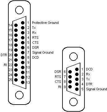
Connection of the PLC to a PC running OPC Server will be via any available COM port, which may be either 25 pin or 9 pin depending on what is available. The PC will only support RS232 mode, an intelligent RS485-to-RS232 converter will be required to connect using RS485 2 wire or 4 wire communications. The COM port pin out is shown below:

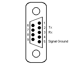
The drive itself has two COM ports, labelled SK1 and PL1. The SK1 port is used for RS232 communications:

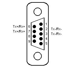
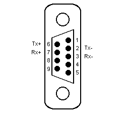
The PL1 port is used for RS485 2 wire and 4 wire communications:


The following shows the correct wiring for connection to the Unidrive PLC:
Examples
Addressing parameter 7 in table 3:
0307
Addressing parameter 5 in table 12:
1205