HMD Multi Drop Communications
This protocol has been written to extract information from a Hitech Metal Detector PLC. Data is transferred using ASCII format.
Details on the device address can be found in the Device Properties Information Topic.
External Address Format
External Address is an ascii string which exactly references an item of data within the PLC. It can be entered at configure time as a text string, and will be validated by the system before use. For this protocol the external address has the following format:
N - Dec number 0 – 9
|
HMD Parameter |
|
NNNNN |
Offset Format
This protocol does not support table and offset style configuration.
Property Pages
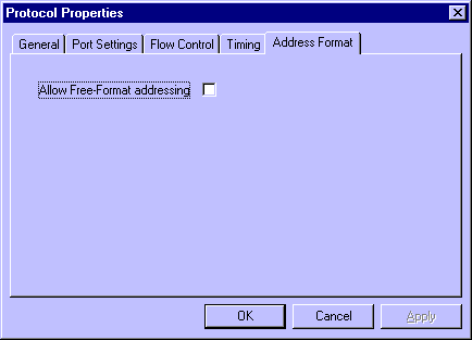
A single protocol specific property page exists in the advanced port settings. The Address Format property page allows the user to select a free-format addressing mode, where the entry defined in the External Address field is not validated by the protocol. This mode should be used with care, since an incorrect entry may cause PLC malfunction. If not used in free-format mode, then the protocol will validate the entry as defined in the External Address section.

Protocol Compatibility
This protocol can operate in two modes – normal or free format. When operating in Normal Mode, the HITECH identifier shown in the table below must be used. When operating in Free Format Mode, any character string may be entered, but the Metal Detector itself may only recognise those commands show in the table below.
|
Description |
HITECH Identifier |
Free Format Identifier |
Read/Write Status |
|
Name of Product |
PRSEL |
PS |
Read Only |
|
Batch Code |
BCODE |
BC |
Read/Write |
|
Accept Total |
ACTTL |
CN |
Write Only |
|
System Status |
SYSST |
SS |
Read Only |
|
Alarm Status |
ALMST |
ALM |
Read Only |
|
Error Status |
ERRST |
ERR |
Read Only |
|
Recipe Select |
RPSEL |
RS |
Read & Write |
|
Reg. Window Begin |
RWBEG |
RB |
Read & Write |
|
Reg. Window End |
RWEND |
RE |
Read & Write |
|
Prod. Limit Begin |
PLBEG |
PB |
Read & Write |
|
Prod. Limit End |
PLEND |
PE |
Read & Write |
|
Insp. Length |
INSPL |
IL |
Read & Write |
|
Insp. Offset |
INSPO |
IO |
Read & Write |
|
Insp. Spot Begin |
ISBEG |
SB |
Read & Write |
|
Insp. Spot End |
ISEND |
SE |
Read & Write |
|
Number Prods. |
NUMPR |
NP |
Read & Write |
|
Reject Offset |
RJCTO |
RO |
Read & Write |
|
Prod. Actual Begin |
PABEG |
AB |
Read Only |
|
Prod. Actual End |
PAEND |
AE |
Read Only |
|
Error Status |
ERSTS |
ER |
Read Only |
|
System Mode |
SYSMD |
SM |
Read Only |
Note: (*)
When writing to the detectors using these parameters, the system will write a zero to reset the detector
total.
Port Settings
|
|
Baud Rate |
4800 |
|
|
Character Bits |
8 |
|
|
Stop Bits |
1 |
|
|
Parity |
NONE
|
Wiring Information
Connection of the unit to a PC running OPC Server will be via any available COM port, which may be either 25 pin or 9 pin depending on what is available. The COM port pin out is shown below:

Please consult your PLC documentation for wiring details at the PLC end.
Examples
Example 1
Read the Name of the Product into the Server System from detector address 01.
|
|
Device Address |
01 |
|
|
External Address |
PRSEL |
Example 2
Write the remote command from the System to detector address 14 in the PLC.
|
|
Device Address |
14 |
|
|
External Address |
RMCOM |
Example 3
Write the batch code from the System to detector address 01 in the PLC.
|
|
Device Address |
01 |
|
|
External Address |
01BCODE |
PLC Specific Error Codes
Under error conditions one or more of the following error codes may be displayed:
|
|
PLC Error Code |
An unexpected error (code n) was received from the PLC |
|
|
Illegal Function |
The PLC did not recognise the requested function |
|
|
Illegal Data Address |
The address specified for a read or write operation is outside the valid range |
|
|
Illegal Data Value |
A written value was outside the acceptable range of values |
|
|
Busy Rejected Message |
The PLC was too busy processing information to respond to the request |