Key Reader
The following applies to NEX701 Serial Key Reader devices.
Details on the device address can be found in the Device Properties Topic
External Address Format
External Address is an ascii string which exactly references an item of data within the PLC. It can be entered at configure time as a text string, and will be validated by the system before use. For this protocol the external address has the following format:
N - Dec number 0 - 9
|
Type |
Offset |
|
D |
NNNNN |
|
L |
NNNNN |
|
W |
NNNNN |
|
R |
NNNNN |
|
K |
NNNNN |
Offset Format
The software also allows an item of data within the PLC to be referenced by means of a table selection and an offset. The following table shows the offset and table formats for the Serial Key Reader:
|
Table |
External Address Type |
Type |
Offset Format |
Offset Range |
Privilege R = Read W = Write |
Description |
|
Data Table |
D |
Byte |
NNNNN |
00000-65534 |
RW |
Key data |
|
Logged Data Table |
L |
Byte |
NNNNN |
00000-65534 |
RW |
Key data in logged format |
|
Write Data Index |
W |
Word |
NNNNN |
00000-65534 |
RW |
Current write position in logged data |
|
Read Data Index |
R |
Word |
NNNNN |
00000-65534 |
RW |
Current read position in logged data |
|
Key Control Table |
K |
Bit |
NNNNN |
00000-00000 |
RW |
Special key control data items |
Property Pages
No property pages exist for this protocol
Protocol Compatibility
The data table consists of bytes and supports the configuration of smaller or bigger point types. All larger point types will read the required number of bytes to fill the point. Bit type points allow the selection of a bit offset to reference the required bit from the byte (0-7). In the case of bit selection points, drive outs will perform a read/modify/write operation, as the protocol does not support a bit set operation in this case.
The logged data table uses the key data as a continuous log. To set up a log on the key simply define a point of any type, choosing an address where the log should start on the key. Driving out to this point will add an entry to the log.
Defining a word point on the write index table at the same address will read back the current log write position, this value is also the number of items which are stored in the log. A value of zero indicates that the log is empty. The write position can be driven to, but should be done carefully, as setting a new value will move the position where the next log write will take place. Setting the write index back to zero will have the effect of starting the log again and writing over the data already stored.
Defining a word point on the read index table at the same address will read back the current log read position. This will be initially zero, which means the no log data is returned. Incrementing this value will have the effect of the next logged value being read back by the log point itself. In order to retrieve all of the data from the log, this value should be incremented until it reaches the value of the write index.
The key control table has a single bit item, when a value of one is driven to this point the key will be erased. Note that this operation takes some time, the write request itself will time out, but the erase will occur a few seconds later.
It is possible to define more than one log on a key. The logs should be defined at different addresses, and be well separated. Great care should be taken not to let the logs run into one another.
Port Settings
The following shows the port setup for the Serial Key Reader device:
RS232
|
|
Baud Rate |
1200/9600 |
|
|
Data Bits |
8 |
|
|
Stop Bits |
1.0 |
|
|
Parity |
None/Even |
Note that baud rate and parity are jumper selectable on the device itself.
Wiring Information
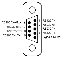
Connection of the key reader to a panel will be via either COM1 or COM2, using RS232 communications. The panel pin out diagram is shown below:

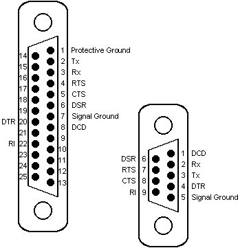
Connection of the key reader to a PC running OPC Server will be via any available COM port, which may be either 25 pin or 9 pin depending on what is available. The COM port pin out is shown below:

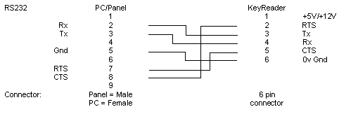
The key reader has a six pin connector on the circuit board. Connection to the key reader requires the following wiring:

Examples
An example of the first data item would be:
D00000
An example of a log configured at address 00100 with read and write index points would be:
L00100 W00100 R00100
The key control bit that erases the key is:
K00000