Mitsubishi FX Programming Port
The following applies to Mitsubishi FX0N, FX0S and FX1N PLC’s running the Mitsubishi FX Programming Port protocol.
Details on the device address can be found in the Device Properties Information Topic.
External Address Format
The External Address is an ascii string which exactly references an item of data within the PLC. It can be entered at configure time as a text string, and will be validated by the system before use. For this protocol the external address has the following format:
O - Octal Number 0 - 7
N - Decimal Number 0 - 9
|
Type |
Offset |
|
X |
OOO |
|
Y |
OOO |
|
M |
NNNN |
|
S |
NNN |
|
TS |
NNN |
|
CS |
NNN |
|
TN |
NNN |
|
CN |
NNN |
|
D |
NNNN |
Offset Format
The software also allows an item of data within the PLC to be referenced by means of a table selection and an offset. The following table shows the offset and table formats for all PLC types.
FX0N
|
Table |
External Address Type |
Type |
Offset Format |
Offset Range |
Privilege R = Read W = Write |
Description |
|
X |
X |
Bit |
OOO |
000-177 |
RW |
Inputs |
|
Y |
Y |
Bit |
OOO |
000-177 |
RW |
Outputs |
|
M (0-255) |
M |
Bit |
NNNN |
0000-0255 |
RW |
Auxiliary Relays |
|
M (256-511) |
M |
Bit |
NNNN |
0256-0511 |
RW |
Auxiliary Relays |
|
M (512-767) |
M |
Bit |
NNNN |
N/A |
RW |
Auxiliary Relays |
|
M (768-1023) |
M |
Bit |
NNNN |
N/A |
RW |
Auxiliary Relays |
|
M (1024-1279) |
M |
Bit |
NNNN |
N/A |
RW |
Auxiliary Relays |
|
M (1280-1535) |
M |
Bit |
NNNN |
N/A |
RW |
Auxiliary Relays |
|
M (8000-8255) |
M |
Bit |
NNNN |
8000-8255 |
RW |
Special Aux Relays |
|
S (0-255) |
S |
Bit |
NNN |
000-127 |
RW |
States |
|
S (256-511) |
S |
Bit |
NNN |
N/A |
RW |
States |
|
S (512-767) |
S |
Bit |
NNN |
N/A |
RW |
States |
|
S (768-1023) |
S |
Bit |
NNN |
N/A |
RW |
States |
|
TS |
TS |
Bit |
NNN |
000-063 |
RW |
Timer Contacts |
|
CS |
CS |
Bit |
NNN |
000-254 (032-234 N/A) |
RW |
Counter Contacts |
|
TN |
TN |
Word |
NNN |
000-063 |
RW |
Timer Current Value |
|
CN |
CN |
Word |
NNN |
000-254 (32-234 N/A) |
RW |
Counter Current Value |
|
D (0-255) |
D |
Word |
NNNN |
0000-0255 |
RW |
Data Registers |
|
D (1000-2499) |
D |
Word |
NNNN |
N/A |
RW |
File Data Registers |
|
D (8000-8255) |
D |
Word |
NNNN |
8000-8255 |
RW |
Special Data Registers |
FX1N
|
Table |
External Address Type |
Type |
Offset Format |
Offset Range |
Privilege R = Read W = Write |
Description |
|
X |
X |
Bit |
OOO |
000-177 |
RW |
Inputs |
|
Y |
Y |
Bit |
OOO |
000-177 |
RW |
Outputs |
|
M (0-255) |
M |
Bit |
NNNN |
0000-0255 |
RW |
Auxiliary Relays |
|
M (256-511) |
M |
Bit |
NNNN |
0256-0511 |
RW |
Auxiliary Relays |
|
M (512-767) |
M |
Bit |
NNNN |
0512-0767 |
RW |
Auxiliary Relays |
|
M (768-1023) |
M |
Bit |
NNNN |
0768-1023 |
RW |
Auxiliary Relays |
|
M (1024-1279) |
M |
Bit |
NNNN |
1024-1279 |
RW |
Auxiliary Relays |
|
M (1280-1535) |
M |
Bit |
NNNN |
1280-1535 |
RW |
Auxiliary Relays |
|
M (8000-8255) |
M |
Bit |
NNNN |
8000-8255 |
RW |
Special Aux Relays |
|
S (0-255) |
S |
Bit |
NNN |
000-127 |
RW |
States |
|
S (256-511) |
S |
Bit |
NNN |
256-511 |
RW |
States |
|
S (512-767) |
S |
Bit |
NNN |
512-767 |
RW |
States |
|
S (768-1023) |
S |
Bit |
NNN |
768-999 |
RW |
States |
|
TS |
TS |
Bit |
NNN |
000-255 |
RW |
Timer Contacts |
|
CS |
CS |
Bit |
NNN |
000-255 |
RW |
Counter Contacts |
|
TN |
TN |
Word |
NNN |
000-255 |
RW |
Timer Current Value |
|
CN |
CN |
Word |
NNN |
000-255 |
RW |
Counter Current Value |
|
D (0-255) |
D |
Word |
NNNN |
0000-0255 |
RW |
Data Registers |
|
D (1000-2499) |
D |
Word |
NNNN |
N/A |
RW |
File Data Registers |
|
D (8000-8255) |
D |
Word |
NNNN |
8000-8255 |
RW |
Special Data Registers |
FX0S
|
Table |
External Address Type |
Type |
Offset Format |
Offset Range |
Privilege R = Read W = Write |
Description |
|
X |
X |
Bit |
OOO |
000-017 |
RW |
Inputs |
|
Y |
Y |
Bit |
OOO |
000-015 |
RW |
Outputs |
|
M (0-255) |
M |
Bit |
NNNN |
0000-0255 |
RW |
Auxiliary Relays |
|
M (256-511) |
M |
Bit |
NNNN |
0256-0511 |
RW |
Auxiliary Relays |
|
M (512-767) |
M |
Bit |
NNNN |
N/A |
RW |
Auxiliary Relays |
|
M (768-1023) |
M |
Bit |
NNNN |
N/A |
RW |
Auxiliary Relays |
|
M (1024-1279) |
M |
Bit |
NNNN |
N/A |
RW |
Auxiliary Relays |
|
M (1280-1535) |
M |
Bit |
NNNN |
N/A |
RW |
Auxiliary Relays |
|
M (8000-8255) |
M |
Bit |
NNNN |
N/A |
RW |
Special Aux Relays |
|
S (0-255) |
S |
Bit |
NNN |
000-063 |
RW |
States |
|
S (256-511) |
S |
Bit |
NNN |
N/A |
RW |
States |
|
S (512-767) |
S |
Bit |
NNN |
N/A |
RW |
States |
|
S (768-1023) |
S |
Bit |
NNN |
N/A |
RW |
States |
|
TS |
TS |
Bit |
NNN |
000-055 |
RW |
Timer Contacts |
|
CS |
CS |
Bit |
NNN |
000-254 (016-234 N/A) |
RW |
Counter Contacts |
|
TN |
TN |
Word |
NNN |
000-055 |
RW |
Timer Current Value |
|
CN |
CN |
Word |
NNN |
000-254 (016-234 N/A) |
RW |
Counter Current Value |
|
D (0-255) |
D |
Word |
NNNN |
0000-0031 |
RW |
Data Registers |
|
D (1000-2499) |
D |
Word |
NNNN |
N/A |
RW |
File Data Registers |
|
D (8000-8255) |
D |
Word |
NNNN |
8000-8069 |
RW |
Special Data Registers |
Property Pages
The following device advanced properties page exists for a Mitsubishi device:
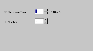
PC response time is the time in units of 10 milliseconds, in which the PLC will expect a response from the panel or PC (the master).
PC number is the network address of the master on the Mitsubishi network. This parameter will not be used in a point-to-point setup.
Protocol Compatibility
A bit type table such as ‘X’ will support the configuration of point types bigger than a bit. If a 16-bit point is configured for example, 16 bits will be read from the table to fill the point. The FX Programming Port protocol does not support writing back of multiple bit points. They will return a comms block error. Only single bit writes are supported on bit tables.
A word type table such as ‘D’ supports the configuration of smaller or bigger point types. All larger point types will read the required number of words to fill the point. Byte type points will scale down the word to fit it into a byte. Bit type points allow the selection of a bit offset to reference the required bit from the word (0-15). In the case of bit selection points, drive outs will perform a read/modify/write operation as the protocol does not support a bit set operation in this case.
Port Settings
RS485 4 wire
|
|
Baud Rate |
9600 |
|
|
Data Bits |
7 |
|
|
Stop Bits |
1.0 |
|
|
Parity |
Even |
Wiring Information
Connection of the PLC to a panel will be via either COM1 or COM2, using RS485 4 wire communications. The panel pin out diagram is shown below:
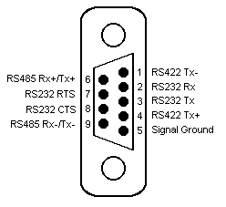
Connection of the PLC to a PC running OPC Server will be via any available COM port, which may be either 25 pin or 9 pin depending on what is available. An intelligent RS485-to-RS232 converter will be required to connect using RS485 4 wire communications. The COM port pin out is shown below:

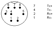
The Programming Port on the Mitsubishi FX PLC has a mini DIN socket which has the following pin out:
The following shows the correct wiring for connection to a Mitsubishi FX PLC through the Programming Port:

Examples
Output Table Last Output on FX0N
Y177
Counter Current Value Last Value on FX0N
CN254