Modbus Slave
The Modbus Slave Protocol is used to communicate with any device which talks Modbus RTU Protocol.
Details on the device address can be found in the Device Properties Information Topic.
External Address Format
External Address is an ascii string which exactly references an item of data within the PLC. It can be entered at configure time as a text string, and will be validated by the system before use. For this protocol the external address has the following format:
N - Dec number 0 - 9
|
Type |
Offset |
|
Bits |
NNN |
|
Registers |
NNN |
Offset Format
The software also allows an item of data within the PLC to be referenced by means of a table selection and an offset. The following table shows the offset and table formats for the Modbus Slave Protocol:
|
Table |
External Address Type |
Type |
Offset Format |
Offset Range |
Privilege R = Read W = Write |
Description |
|
Bits |
Bits |
Bit |
NNN |
000-800 |
RW |
Digital Data |
|
Registers |
Registers |
Word |
NNN |
001-500 |
RW |
Analogue Data |
Property Pages
No property pages exist for this protocol
Protocol Compatibility
The bit type table ‘B’ will support the configuration of point types bigger than a bit. If a 16-bit point is configured for example, 16 bits will be read from the table to fill the point. The Modbus Slave protocol fully supports writing back multiple bit points.
The word type table ‘R’ supports the configuration of smaller or bigger point types. All larger point types will read the required number of words to fill the point. Byte type points will scale down the word to fit it into a byte. Bit type points allow the selection of a bit offset to reference the required bit from the word (0-15). In the case of bit selection points, drive outs will perform a read/modify/write operation as the protocol does not support a bit set operation in this case.
Port Settings
The port settings are variable depending on the settings of the Modbus master. The following shows a typical port setup:
RS232
|
|
Baud Rate |
9600 |
|
|
Data Bits |
8 |
|
|
Stop Bits |
1.0 |
|
|
Parity |
Even |
Wiring Information
The Modbus Slave protocol is designed to collect information from another Panel or PC running a Modbus RTU protocol. Panel-to-Panel connection can use either RS232 or RS485 4 wire communications. In a multi-drop setup it is possible to have several devices communicating through Modbus Slave talking to only one device talking Modbus RTU.
DO NOT use RS485 2 wire communications with this protocol..
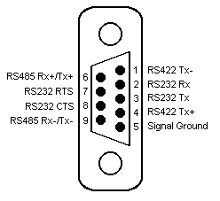
The COM port on the panel has the following pin out:

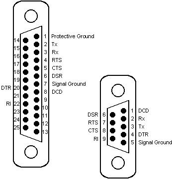
Connection of PC to PC or Panel to PC will usually be RS232 communications. The PC COM port pin out is shown below:

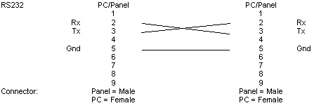
The following shows the correct wiring for connection to a device running the Modbus RTU Protocol, by a device running the Modbus Slave Protocol:


Example
An example of the External Address for the 15th Bit would be:
B015